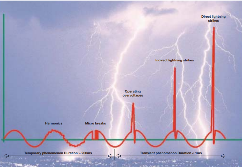
Why a surge protective device required?
As the name suggests, Surge Protective Devices are used to protect the Electrical Installations from transient over voltages what we called as voltage surges. These transient over voltages are defined as electrical surges lasts for short duration occurred due to sudden release of energy which is previously stored or induced either naturally occurring or man-made.
A voltage surge can result in either instant failure of the installation or cause an eventual failure only evident over a longer period of time. Despite that it can cause,
- Serious injuries or loss of human life
- Interruption of essential services or public services
- Interruption of commercial or industrial functions
In short terms Surge Protective Devices are called as SPDs and these can protect our valuable electrical installations such as wiring, switchgears, wired equipment’s, fire detection systems and emergency lighting, sensitive electronic items and machineries from these voltage surges coming through our electrical supply.
Some SPDs are is connected parallel to your network and the basic operation of this is, it has a high impedance in normal conditions and once a transient overvoltage appears in the power lines due to lightning or switching of motors and transformers, the impedance of the surge protective device will be decreased and it allows to drive the surge current through it divert it to the earth. Hence the sensitive equipment in your system doesn’t get any damage.
Note: Some of the Type 3 SPDs are connected in series to the electrical supply.
Ex. Sensitive Electronics, Telecommunication lines
Type 1+2:
These combined Type 1 & 2 SPDs designed to protect the electrical installations for direct and indirect lightning. Type 1+2 SPDs are characterized for 10/350 µs and 8/20 µs current waveforms.
Type 3:
Type 3 SPDs are having a low discharge capacity and due to that they must be installed therefore as a supplement to Type 2 SPD. These are installed parallel to the electrical circuit as well as series to the electrical circuit in order to protect the sensitive and valuable electrical equipment’s from transient currents. In telecommunication lines these are connected in series. These should be located near the sensitive loads which needs to be protected in coordination with Type 2. Type 3 SPD is characterized for the combination of voltage waves having 1.2/50 μs and current waves of 8/20 μs.
Type 2+3:
Type 2+3 SPDs are installed just before the protected equipment and these are having similar characteristic to the Type 3 SPD. Because when a type 3 SPD is installed primary protection is provided with the type 2 due to its low discharging capacity
Type 2+3 SPDs are characterized for combination of voltage waves 1.2/50 μs and current waves with 8/20 μs which is similar to the Type 3.
Where it requires the coordination of SPDs,
When SPDs are installed at your installation, coordination of the short circuit levels of each SPD should be adhered. Further the coordination of external short circuit protection equipment’s like breakers and fuses also need be considered. As per the IEC 60364 the external SCPD should have a breaking capacity equal to or greater than the prospective short-circuit current at the installation.
Sometimes additional SPDs protection need to be added to your installation at the following occasions,
- When the incoming surge arrester is unable keep the required protection voltage (Up).
- When the incoming surge arrester is located more than 10m away from the equipment to be protected.
How a distance of 10m is significant from incoming SPD to the equipment?
That is due to the wave reflection phenomena in the cable. When a lightning wave is propagating through a cable due to the reflection phenomena caused by different impedances of two medium or due to cable length, the voltage can be doubled at a length of 10m to 30m. Hence it is desirable to have an additional SPD protection for the equipment if the cable length exceeds 10m from the SPD to the equipment should be protected.
Various Mode of Propagation: Common Mode Overvoltage & Differential Mode Overvoltage
Common-mode overvoltage appears between live conductors and earth as phase-to-earth or neutral-to-earth. Differential-mode overvoltage appears between live conductors as phase-to-phase or phase-to-neutral.
According to the Earthing arrangement of the installation the required SPD architecture has to be decided whether common mode or differential mode protection should inculcate in the SPD. The following table shows the necessity of mode of protection as per the Earthing arrangement.
[1] – Inculcate in the SPD at the origin of the installation or close to the equipment to be protected
[2] -If the Neutral is distributed
Short Circuit Current Rating (SCCR) of the SPD
This SCCR indicates the maximum fault current that the SPD can withstand at rated voltage without causing any damage. SCCR is not related to the surge rating but it indicates the maximum allowable current that SPD can interrupt at fault conditions.
- Residential – 5kA-10kA
- Small Commercial – 14kA-42kA
- Large Commercial/ Industrial – 42kA-100kA
References:
- https://www.electrical-installation.org/enwiki
- https://electrical.theiet.org/courses-resources-career/free-resources/consumer-guidance/surge-protective-devices/
- https://www.google.com/url?sa=t&rct=j&q=&esrc=s&source=web&cd=&cad=rja&uact=8&ved=2ahUKEwjYiMHWn9j6AhUl3jgGHRfxBTwQFnoECCAQAQ&url=https%3A%2F%2Flibrary.e.abb.com%2Fpublic%2Ff1d312ec7475f837c1256ef5003024fb%2FFRSOX_0201_04-GB.pdf&usg=AOvVaw20Ir56j1dQuf3KPCIVtGv0